Engineering 44 - Cesar Bazua
Wednesday, June 12, 2013
Monday, June 10, 2013
Impedance and AC Analysis
Impedance and AC Analysis
Introduction
The purpose of this lab is to analyze inductors and the affect that changing frequencies can have on the impedance in a circuit.
Procedure
We set up the following circuit
 |
The function generator was set to generate 5V at 1000 Hz
We measured each component and garnered the following values:
R_L = 8.3 Ω
R_ext = 67.2 Ω
V_in,rms = 4.93 V
I_in,rms = 65.0 mA
Note: The voltage reading differs from the function generator because of its internal resistance
We then used the measured values to complete the following calculations:
V_in/I_in = Z_L = 75.8 Ω
Z_L = sqrt((R_ext + R_L)^2 + (ωL)^2)
ω = 2πf = 6280 rad/s
L = 1.16 mH
We then found the value of a capacitor needed to cancel the impedance provided by the inductor
1/ωC = ωL
C = 1/(ω^2*L) = 2.19 *10^-5 F
We then built the following circuit:
 |
V_pp, CH1 = 1.5V
V_pp, CH2 = 20mV
deltaT = 0.4 ms
Phase difference = (deltaT) *6240* 360 ° = 184.32 °
Analysis
Frequency (kHz)
|
V_in (V)
|
I_in (A)
|
|Z_in| (Ω)
|
5
|
4.6
|
0.073
|
63.0137
|
10
|
4.2
|
0.0719
|
58.41446
|
20
|
3.51
|
0.0691
|
50.79595
|
30
|
3.51
|
0.0653
|
53.75191
|
50
|
4.5
|
0.0558
|
80.64516
|
1. The largest current should be seen at 1 kHz, as this is when the imaginary part cancels out.
2. V_L = Z_L/Z*V_in
V_L = 2.8574 + 1.2737j
Phasor = 24.0243 °
3. The circuit is more capacitive at frequencies below 1kHz because of the fact that the impedance provided by the capacitor increases when frequency is decreased.
4. The circuit is more inductive at frequencies above 1kHz because of the fact that the impedance provided by the inductor increases when frequency is increased.
4. The circuit is more inductive at frequencies above 1kHz because of the fact that the impedance provided by the inductor increases when frequency is increased.
Wednesday, May 22, 2013
Complex Numbers Matlab
MOSFET
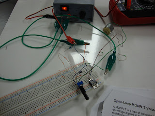
The objective of this activity is to control the speed of an electric motor by using a MOSFET.
This is circuit is first assembled
The resistance being output by the potentiometer causes the voltage that is supplied to the motor to vary thereby controlling its speed. the motor turned on when at least 3.9 V were being delivered to it.
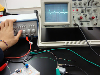
We set the function generator to produce square waves at 10 KHz while its duality was set to be on. We then used an oscilloscope to displace the waveform of the motor voltage.
 |
Lastly,the frequency was reduced to a few Hertz, at which point the motor turns on and off depending on the amplitude of the square-wave.
Finally, both the potentiometer and the function generator were able to achieve motor speed control. The function generator was much more effective due to its increased precision, thereby making specific motor speeds more achievable..
Second Order Circuits
Oscilloscopes
Introduction to Oscilloscopes
Purpose: To explore the properties and applications of O-ScopesIntroduction:
the following is used
an Oscilloscope
a Function Generator set to 5kHz sine wave and 5 Volts
a DMM
The oscilloscope was adjusted to show about 2 periods and above the x-axis. The period is 200 microseconds. The voltage was adjusted to have a peak-to-peak voltage of 5 volts. The was a measured DC voltage of 0V and an AC voltage of 1.05V.

The DC offset was set on the Function Generator measured a DC voltage of 2.517V and an AC voltage of 1.051V. It showed the following:

The function generator was then used display square waves. The square waves gave a DC voltage of 2.516V and and AC voltage of 1.375V. The Oscilloscope displayed the following:
Lastly, A mystery signal was given in for us to "find".Once the oscilloscope was properly adjusted.we saw the following:

From this we identified the signal as a time varying ramp function!
Oscilloscopes can show voltage in a circuit as well as how it varies with time. It can also calculate frequency and allows one to focus on certain parts of a signal.
Capacitors
Capacitor Charging/ Discharging
Purpose
To examine the charging and discharging of a capacitor circuit using thevenin equivalences.
We have to circuits, one for charging and one for discharging.

The goal is to design build and test a circuit that does the following:
1.utilizes a 9V power
2. Employs a charging interval of 20s with a stored energy of 2.5mJ
3. discharges the 2.5mJ in 2s
To fulfill these requirements we have the following for charging resistance and capacitance

The peak current, discharge and resistance were then determined.

the actual values used were.

the circuit was the built.

logger pro was then used to record the results

Data:
Charging Curve.

The capacitor saturates at around 8.5V due to its internal resistance.
Discharge curve.

Its not done completely in 2 secs but it is close.
he charging and discharging of capacitors is exponential and the time to make them discharge and charge can be easily controlled by changing the value of the resistance and/or capacitors.

Subscribe to:
Comments (Atom)


