Wednesday, May 22, 2013

Complex Numbers Matlab


MatLab and Complex Numbers

To understand how to work with complex numbers in MatLab.


1) Example with simple functions


2) Finding Magnitude and Phase angle


Assignment 1)


Assignment 2)


Assignment 3)


Assignment 4)


MOSFET


The objective of this activity is to  control the speed of an electric motor by using a MOSFET.


This is circuit is first assembled


The resistance being output by the potentiometer causes the voltage that is supplied to the motor to vary thereby controlling its speed. the motor turned on when at least 3.9 V were being delivered to it.

We then replaced the potentiometer with a function generator.

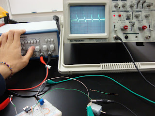
We set the function generator to produce square waves at 10 KHz while its duality was set to be on. We then used an oscilloscope to displace the waveform of the motor voltage. 


Lastly,the frequency was reduced to a few Hertz, at which point the motor turns on and off depending on the amplitude of the square-wave.


Finally, both the potentiometer and the function generator were able to achieve motor speed control. The function generator was much more effective due to its increased precision, thereby making specific motor speeds more achievable..

Second Order Circuits

Second Order Circuits


Objective: To go through various steps to understand how to do a second order circuit problem.

We went through the "Second Order Systems" example at http://www.mhhe.com/engcs/alexander2e/netan_tutorials/tutorials/tutmenu.htm


Oscilloscopes


Introduction to Oscilloscopes

Purpose: To explore the properties and applications of O-Scopes
Introduction:
      the following is used

an Oscilloscope
a Function Generator set to 5kHz sine wave and 5 Volts
a DMM


     The oscilloscope was adjusted to show about 2 periods and above the x-axis. The period is 200 microseconds. The voltage was adjusted to have a peak-to-peak voltage of 5 volts. The was a measured DC voltage of 0V and an AC voltage of 1.05V.


    The DC offset  was set on the Function Generator measured a DC voltage of 2.517V and an AC voltage of 1.051V. It showed the following: 


    The  function generator was then used display square waves. The square waves gave a DC voltage of 2.516V and and AC voltage of 1.375V. The Oscilloscope displayed the following:


    Lastly, A mystery signal was given in for us to "find".Once the oscilloscope was properly adjusted.we saw the following:


 From this we identified the signal as a time varying ramp function!


Oscilloscopes can show voltage in a circuit as well as how it varies with time. It can also calculate frequency and allows one to focus on certain parts of a signal.

Capacitors

Capacitor Charging/ Discharging

Purpose
To examine the charging and discharging of a capacitor circuit using thevenin equivalences.

We have to circuits, one for charging and one for discharging.


The goal is to design build and test a circuit that does the following:

1.utilizes a 9V power
2. Employs a charging interval of 20s with a stored energy of 2.5mJ
3. discharges the 2.5mJ in 2s
   To fulfill these requirements we have the following for charging resistance and capacitance


The peak current, discharge and resistance were then determined.

the actual values used were.

 
the circuit was the built.

logger pro was then used to record the results 


Data:

Charging Curve.

The capacitor saturates at around 8.5V due to its internal resistance.

Discharge curve.

Its not  done completely in 2 secs but it is close.

he charging and discharging of capacitors is exponential and the time to make them discharge and charge can be easily controlled by changing the value of the resistance and/or capacitors.


Op-Amps II

Op Amps II

Purpose: To observe the effects varying the feedback and input resistances in an op amp circuit.

In order to determine what resistors to use calculations were performed to obtain a gain of 10 and 0.1mA current.
 The circuit was then built and Vs was adjusted to 0.25 V using a voltage divider as shown.

A 1kΩ resistor was then  placed as the load.


Voltages were then recorded across all resistors using this set-up.

The following data was obtained

For V_IN = 1V 
       Measured I_cc = 0.867 mA 
                Calculated P_cc = 12*0.867 mP = 10.404 mP
       Measured I_ee = -0.979 mA 
                 Calculated P_ee = 12*0.979 mP = 11.748 mP

       I_cc + I_ee = 0.112 mA
       The percent error is 12% therefore, it is consistent with KCL.

  For V_IN = 1V 

    Measured I_cc = 0.877 mA 
            Calculated P_cc = 12*0.877 mP = 10.524 mP
    Measured I_ee = -0.984 mA 
             Calculated P_ee = 12*0.984 mP = 11.808 mP
     I_cc + I_ee = 0.107 mA
     The percent error is 07% therefore, it is consistent with KCL


Finally,  With percent errors of 12% and 7% this experiment is considered a success and obeys Kirchhoff's Current Law. We saw that the gain depends directly on Rf/Ri.